

plug and play
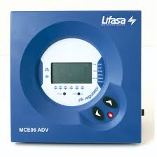
When a power factor controller is installed, a number of parameters need to be set up for a proper operation. Some of these parameters might be hard to know, such as, for example, the voltage phases or the correspondence of the measured current with its voltage, as well as the current transformer ratio. Controller MCE ADV incorporates a smart automatic process that detects the necessary parameters, such as:
Phase
Installation and polarity of the CT (Current Transformer). The controller allows the user not to have to change phase location where the TC (X/5) is located and/or the reading direction/polarity. The adjustment can be made via the menu on the controller display.
MCE ADV incorporates a LED and an output relay to warn in case that any of the following circumstances happens:
(Note: to perform alarm relay it is necessary to have available one step relay).
| Product or component type | : Power factor correction |
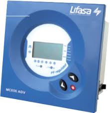
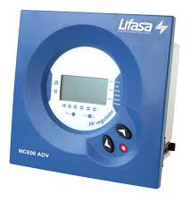
| Application | : Power factor controllers MCE-6 ADV (6 steps) and MCE-12 ADV (12 steps) measure the cos ? of a supply system and control the automatic connection and disconnection of compensation capacitors, according to desired cos ?. |
| Frequency | : 4565 Hz |
| Operating temperature | ; -10 to +50 C |
| Dimension | : 144×144 mm |
| Mounting | : Panel mounting |
| IP rating | : IP 40 |
| Warranty | : 12 months |
| Brand | LIFASA |
| Model Number | MCE12ADV400 |
| SUPPLY VOLTAGE | 480V |
| NO: OF STEPS | 12 STEP |
| TYPE | SMART REGULATOR |
| SIZE | 144×144 mm |
| MOUNTING | PANEL MOUNT |
Mention 800buildingmaterials when calling supplier to get a BEST DEALS